How to Use a Multimeter

Troubleshoot electrical problems to expand your DIY skills

Paul Pogue
Written by Paul Pogue
Updated April 29, 2022
Man reading multimeter at home
Photo: AndreyPopov / Getty Images
Difficulty

Easy

No experience? No problem.

Time to complete

10 minutes

Need professional help with your project?
Get quotes from top-rated pros.

What you'll need:

TOOLS

  • Multimeter

SUPPLIES

  • AAA or AA batteries (optional)

Need to check the life of a battery? Or do you need to diagnose a problem with wiring to an outlet in your home? A digital multimeter tester can help you solve these problems, which is why it’s a useful instrument to keep in your toolbox. A multimeter can be used to troubleshoot a wide variety of issues, and you can use this guide to learn how to use a multimeter in various DIY scenarios.

What Is a Multimeter and How Is It Used?

A multimeter, sometimes referred to as a volt-ohm meter, is a versatile tool for homeowners to keep on hand that tests different units of electricity—voltage (AC and DC), current, and resistance. 

  • Voltage: Measured in volts, alternating current (AC) and direct current (DC), are two forms of voltage that a multimeter can test for. AC is the flow of an electrical current that changes directions, usually found in the electrical wiring throughout your home. DC is the flow of an electrical charge in one direction, normally used in batteries, vehicles, and other electronics.

  • Current: Current, which is measured in amps or amperage, tests the strength of a current to determine the amount of electricity that is flowing through a circuit. It’s an important safety measure to test the amount of current when you’re doing an electrical project, such as wiring a light switch, to ensure the electricity is completely off.

  • Resistance: Measuring resistance determines the opposite flow of electricity, using ohms as the unit of measurement. Resistors are most commonly used in household appliances and electrical devices. 

  • Continuity: Continuity testing measures for a complete path of current. All circuits need a continuous path for electricity to flow through. For example, if an appliance fails, it could be because there’s an open circuit, meaning it’s devoid of continuity. Replacing the component could fix the appliance, allowing it to work properly again.

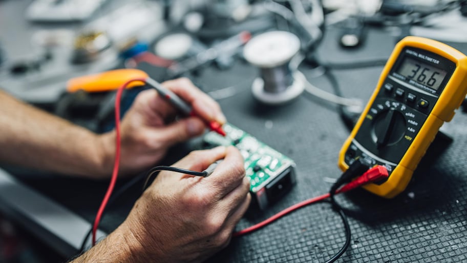
There are digital multimeters and analog multimeters that both perform the same function, but have a different display. A digital multimeter features an LCD display, whereas an analog multimeter has a needle that moves over a numerical scale. 

Anatomy of a Multimeter

Close up of a multimeter
Photo: krisanapong detraphiphat / Getty Images

Learn about the different parts of a multimeter. Remember, the features can differ from model to model, so your multimeter may not have the exact same options as the ones listed.

  • Display: The display is the LCD screen (digital) or scale (analog) that depicts the reading of the electrical measurement. 

  • Selection knob or button: This is the knob or button that allows you to switch between different units of measurement. Here are some of the abbreviations that you may see on your multimeter:

    • AC volts (V with a wavy line over it)

    • DC volts (V with three hyphens and a straight line on top)

    • Resistance (ohms or Ω)

    • Amps (A)

    • Milliamps (mA)

    • Continuity (diode symbol or a soundwave symbol)

  • Hold button: The hold button is used to keep track of a certain reading on the display, so you don’t need to write it down to recall the measurement at a later time. 

  • Test probes: On a multimeter, there are two probes (also referred to as test leads) that are plugged into the ports with a male banana jack to test the electrical component. On the other end of the probe is a metal tip—sometimes referred to as the terminal. The red probe tests for a live current, and the black probe tests ground or neutral terminals. 

Ports: Most multimeters have two or three ports to connect the leads to. All multimeters will have a common port, which is black, and labeled as COM for common. This is where the black probe will plug into. The mAVΩ port is the port that the red probe plugs into and used to test most electrical measurements, such as volts, resistance, and current. The mAVΩ port may also be labeled as VΩ or V. Your multimeter may also have a red 10A port, but it is used less often than the mAVΩ port and typically tests large currents (up to 10 amps).

Safety Precautions and Preparations

Now that you understand the basic uses and components of a multimeter, it’s important to take adequate safety measures when performing electrical work. 

  • Inspect the multimeter for any signs of damage, such as cracks, dings, or leaks, to ensure a safe and accurate reading.

  • Wear insulated gloves and rubber shoes to add a layer of protection when performing electrical tests.

  • Don’t test any wires that are damaged or frayed.

  • Only perform electrical testing in dry conditions.

  • Never touch the metal tips of the probes with your hands.

  • Ensure the multimeter probes are working properly internally by “ohming-out” the leads. Put the multimeter in the resistance (ohms or Ω) setting, then connect the probes to the port (plug the black probe into the COM or common port and plug the red probe into the red mAVΩ port). Touch the tips of the probe together (making sure not to touch the tips with your hands), and check that the reading is 0.5 ohms or less. If the reading is over 0.5 ohms, you will need to replace the probes.

  • Always keep the multimeter in its case when not in use.

4 Ways to Use a Multimeter

Follow this guide to learn how to use a multimeter to measure AC or DC voltage, resistance, and continuity.

  1. Measuring AC Voltage

    Measuring the voltage of an outlet with a multimeter
    Photo: wattanaphob / Getty Images

    Measuring AC voltage is one of the most common uses for a multimeter, and can read a standard three-prong wall outlet to identify any potential wiring problems. 

    • To measure the AC voltage, turn the selection knob to AC volts, beginning at the higher range and adjusting down as you progress. 

    • If you’re testing an outlet, start by turning off the power to the plug from the circuit breaker. 

    • Then, connect the black probe to the common jack, and plug the red probe into the AC voltage port on the multimeter. 

    • Identify the outlet you’re testing and look for the wide and narrow slot. On a polarized plug, the wider prong is neutral and the thinner probe is the live or hot prong. 

    • Put the black probe (or the negative terminal) into the neutral prong and the red probe (or the positive terminal) into the hot prong. 

    • Check the reading on the display of the multimeter. 

    • The measurement should read around 120 volts, and if not, there’s likely a wiring issue.

    • Once you have the reading, remove the red probe first, then remove the black probe.

    • Unplug the test probes from the ports on the multimeter in the same order—red first, then black.

  2. Measuring DC Voltage

    Using a multimeter to measure the voltage of batteries
    Photo: Tamer ALKIS / Getty Images

    Measuring the DC voltage can be used to read batteries—including a car battery.

    Remember, if you’re testing a car battery, turn the headlights on for two minutes, then turn them off to drain the battery enough to determine whether or not there is enough voltage left to power the vehicle efficiently. 

    • Disconnect the battery from the power supply.

    • Switch the selection knob to the DC voltage setting at the expected measurement on the multimeter, which can be determined by looking at the manufacturer’s label. For example, an AA or AAA battery will have a voltage indicator on the side of the label indicating 1.5V.

    • Touch the black probe to the negative side of the battery, and touch the red probe to the positive side.

    • Read the measurement on the display.

    • Remove the red probe first, then the black from the battery. Then, remove the jacks from the multimeter in the same order—red then black.

  3. Measure Resistance

    Man using a multimeter to measure resistance
    Photo: Hirurg / Getty Images

    Measuring resistance can check an electrical component’s resistor and determine if repairs are necessary.

    • Disconnect the device or component from any source of electricity, such as circuits, plugs, or batteries, so there isn’t a flow of current. 

    • Check the resistance value of the resistor based on the manufacturer’s guidelines or the label of the component.

    • Switch the selection knob to the ohms (Ω) setting at the expected resistance level on the scale. 

    • Plug the black probe into the COM jack, and plug the red probe into the mAVΩ port. 

    • Touch both the red and black terminals to the sides of the component you’re testing. It’s important to note that positive and negative doesn’t matter when you’re testing resistance. 

    • Read the measurement on the display. Remember, the test probes carry about 2 ohms of resistance, so you can subtract two from the reading to determine the final measurement. 

    • If the reading on the multimeter matches the suggested resistance value, the resistor is in good condition. Otherwise, it will need to be replaced.

  4. Test the Continuity

    Depending on the multimeter, there may be a continuity setting. Continuity testing allows you to determine if there is a complete path of current flow in a switch, electrical connection, fuse, or conductor. Moreover, you can use check continuity to determine if a power cord is functional or not. 

    • Set the selection knob to the continuity setting.

    • Plug the black probe into the COM port and the red probe into the mAVΩ port.

    • Touch the tips of the red and black terminals together, and look for a number that is zero or close to zero on the display—this indicates that there is continuity. 

    • Place one terminal one one side of the electrical component you’re testing, and place the other terminal on the other end of the component. If the number is zero or close to zero, there’s continuity.

    • If there’s no continuity, the multimeter will display “OL” or “open loop.” This indicates that the component needs to be replaced.

Need professional help with your project?
Get quotes from top-rated pros.